Create and Use an SLR Bridge
The goal of this tutorial is to combine a RapidWright generated circuit with a Vivado design.
Background
In this example, we implement a 4-to-1 TDM (Time-division Multiplexing) design that reduces the number of valuable SLR (Super Logic Region) crossing resources by 4X. SLR crossing resources (super long lines or SLLs) are inter-die connectivity resources within the package and are often in high demand. RapidWright can generate a highly tuned SLR bridge within seconds as a drop-in implementation (.DCP) capable of running at near-spec performance (~750MHz). This tutorial will demonstrate how to use such a bridge and maintain high performance in common design flows.
The TDM circuit and its connectivity with a RapidWright SLR bridge is shown in the figure below.
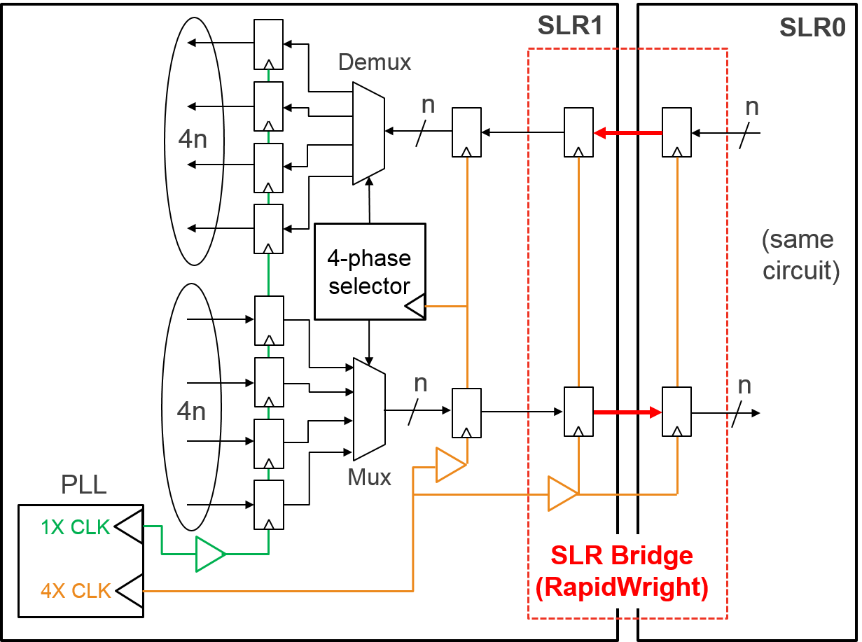
The TDM circuit switches between 4 low frequency signals (1X CLK) to drive data into the faster clock domain (4X CLK), and vice versa. The red-dotted line shows the boundary and encompasses the circuit that will be generated directly from RapidWright. Due to the challenging nature of crossing SLRs, RapidWright has a dedicated circuit generator for SLR crossings that can custom route the clock to avoid hold time issues and minimize inter-SLR delay penalties to provide an implementation that achieves high performance (>700MHz).
By taking this approach, greater bandwidth over the SLR boundaries can be achieved and/or minimizing the total number of SLLs used–leaving them available for other applications such as when building a shell.
Getting Started
Building the Bridge
Begin by creating a directory for our work in this tutorial:
mkdir bridge_tutorial
cd bridge_tutorial
Our first task is to generate an SLR crossing bridge from RapidWright. RapidWright has a dedicated generator for this purpose called the SLRCrossingGenerator which can be run from the command line. To invoke the help/options output of the tool simply run:
rapidwright SLRCrosserGenerator -h
This should produce the following output:
==============================================================================
==                        SLR Crossing DCP Generator                        ==
==============================================================================
This RapidWright program creates a placed and routed DCP that can be
imported into UltraScale+ designs to aid in high speed SLR crossings.  See
RapidWright documentation for more information.

Option                                   Description
------                                   -----------
-?, -h                                   Print Help
-a [String: Clk input net name]          (default: clk_in)
-b [String: Clock BUFGCE site name]      (default: BUFGCE_X0Y218)
-c [String: Clk net name]                (default: clk)
-d [String: Design Name]                 (default: slr_crosser)
-i [String: Input bus name prefix]       (default: input)
-l [String: Comma separated list of      (default: LAGUNA_X2Y120)
  Laguna sites for each SLR crossing]
-n [String: North bus name suffix]       (default: _north)
-o [String: Output DCP File Name]        (default: slr_crosser.dcp)
-p [String: UltraScale+ Part Name]       (default: xcvu9p-flgb2104-2-i)
-q [String: Output bus name prefix]      (default: output)
-r [String: INT clk Laguna RX flops]     (default: GCLK_B_0_1)
-s [String: South bus name suffix]       (default: _south)
-t [String: INT clk Laguna TX flops]     (default: GCLK_B_0_0)
-u [String: Clk output net name]         (default: clk_out)
-v [Boolean: Print verbose output]       (default: true)
-w [Integer: SLR crossing bus width]     (default: 512)
-x <Double: Clk period constraint (ns)>
-y [String: BUFGCE cell instance name]   (default: BUFGCE_inst)
-z [Boolean: Use common centroid]        (default: false)
As you can see, this generator has several parameterizable options. In this case, we will want a bridge that provides 32 wires in both directions using a single column of Laguna tiles. We will use the xcvu7p-flva2104-2-i part for our example and use the far edge Laguna column for our crossing. As RapidWright must custom route the clock to preserve the carefully tuned leaf clock buffer delays, it must include a BUFGCE instance. We also specify the location of the BUFG to improve timing reproducibility in the application context. To generate such a bridge run the following at the command line:
rapidwright SLRCrosserGenerator -l LAGUNA_X20Y120 -b BUFGCE_X1Y80 -w 32 -o slr_crosser_vu7p_32.dcp -p xcvu7p-flva2104-2-i
After several seconds, a new file, slr_crosser_vu7p_32.dcp should appear in our working directory, let’s open it in Vivado to examine what we have created.
vivado slr_crosser_vu7p_32.dcp
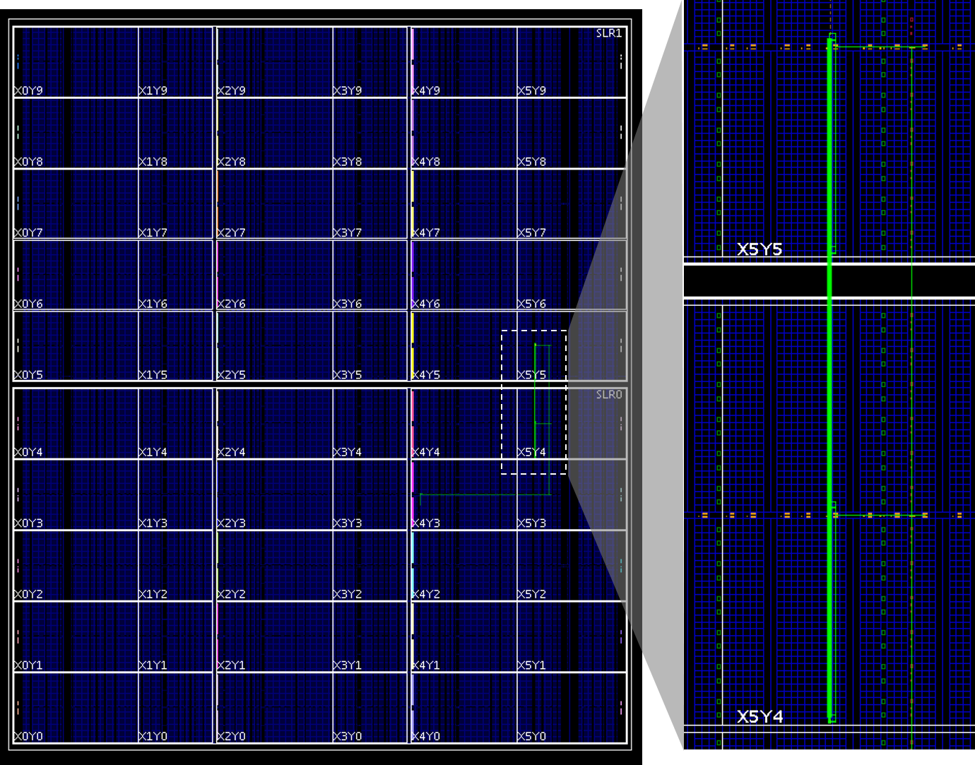
Once open, the device view (Window->Device) should look something like this:
We can also add a timing constraint to test the pre-implemented performance of the bridge with the following Tcl commands:
create_clock -name clk -period 1.333 [get_nets clk]
report_timing_summary -delay_type min_max -report_unconstrained -check_timing_verbose -max_paths 10 -input_pins -routable_nets -name timing_1
We have specified a 750MHz clock constraint (1.333 ns period) and the timing report should show postive slack for both setup and hold. Close this design in Vivado once you are done (don’t save your changes):
close_design
Combining the Designs
Now that we know we have a correct bridge, we can begin on our main
design. To do so, we have provided a synthesized version of our TDM
circuit where N=32. To open synth32_BB.dcp, run the following Tcl commands in Vivado’s
Tcl prompt:
exec wget http://www.rapidwright.io/docs/_downloads/synth32_BB.dcp
open_checkpoint synth32_BB.dcp
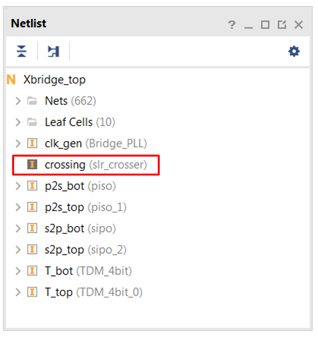
Look at the Vivado netlist view of the synth32_BB.dcp design. The SLR Bridge (crossing instance) has been left open as a black box to be populated with our RapidWright bridge implementation, see the screenshot below for reference:
Note
For ease of use of this tutorial, we have provided a synthesized circuit with a black box. However, in common practice, the generated DCP from RapidWright can simply be instantiated in Verilog/VHDL directly and the DCP added to the sources of the project.
To import our SLR bridge, we will use the read_checkpoint command at the Tcl prompt:
read_checkpoint -cell crossing slr_crosser_vu7p_32.dcp
Note that the netlist icon next to crossing should change from dark to white. The black box has now been populated with our custom SLR bridge implementation we just created in RapidWright.
Implementation
We can now proceed to constrain the design and run place and route by
sourcing the run_PnR.tcl script in
Vivado by running the following Tcl commands in Vivado’s Tcl prompt:
exec wget http://www.rapidwright.io/docs/_downloads/run_PnR.tcl
source run_PnR.tcl
Alternatively, you can copy and paste the contents of the Tcl file below into the Tcl console in Vivado:
# Add pblocks
create_pblock pblock_top
add_cells_to_pblock pblock_top [get_cells [list T_top]] -clear_locs
resize_pblock [get_pblocks pblock_top] -add {CLOCKREGION_X5Y5:CLOCKREGION_X5Y5}
create_pblock pblock_bot
add_cells_to_pblock pblock_bot [get_cells [list T_bot]] -clear_locs
resize_pblock [get_pblocks pblock_bot] -add {CLOCKREGION_X5Y4:CLOCKREGION_X5Y4}
# Implement design and save
place_design
route_design
write_checkpoint -force routed_32.dcp
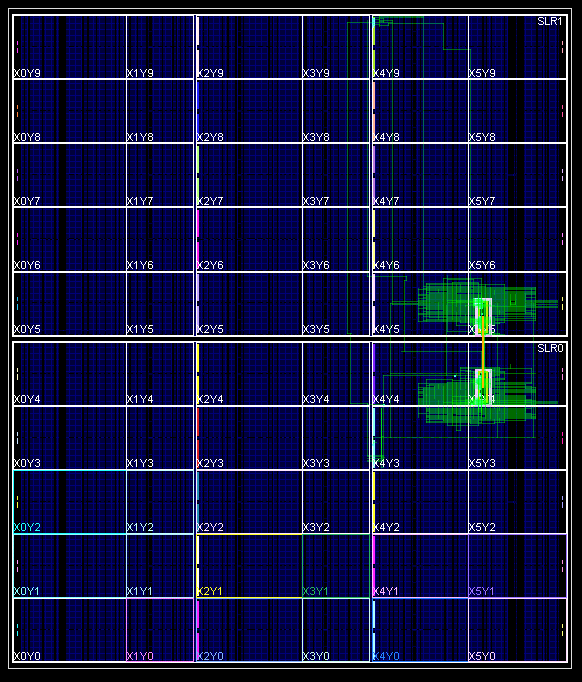
This can take several minutes (up to 30 minutes inside the tutorial virtual machine). For those wishing to skip ahead, we have provided our own implementation of the results of the above Tcl commands here: routed_32.dcp. In the Device model view, our implementation looks like this:
For additional analysis of timing reports can be performed on the
specific paths crossing the SLR and leading up to it by sourcing the run_timing.tcl script in Vivado
by running the following Tcl commands in Vivado’s Tcl prompt:
exec wget http://www.rapidwright.io/docs/_downloads/run_timing.tcl
source run_timing.tcl
Alternatively, you can copy and paste the contents of the Tcl file below into the Tcl console in Vivado:
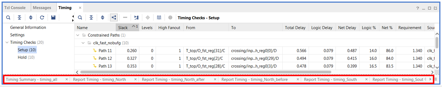
# report to GUI
report_timing_summary -delay_type min_max -report_unconstrained -check_timing_verbose -max_paths 10 -input_pins -routable_nets -name timing_all
report_timing -from {*/input0_north_reg*} -delay_type min_max -max_paths 10 -sort_by group -input_pins -name timing_North
report_timing -from {*/output0_north_reg*} -delay_type min_max -max_paths 10 -sort_by group -input_pins -name timing_North_after
report_timing -to {*/input0_north_reg*} -delay_type min_max -max_paths 10 -sort_by group -input_pins -name timing_North_before
report_timing -from {*/input0_south_reg*} -delay_type min_max -max_paths 10 -sort_by group -input_pins -name timing_South
report_timing -from {*/output0_south_reg*} -delay_type min -max_paths 10 -sort_by group -input_pins -name timing_South_after
report_timing -to {*/input0_south_reg*} -delay_type min_max -max_paths 10 -sort_by group -input_pins -name timing_South_before
This will produce several tabs in the Timing window tab as shown below:
The clock constraint for the design is 1.4ns and our implementation met timing with 0.02ns of positive slack, meaning it can be implemented with a >710MHz fast (4X) clock. This is quite close to the spec of the VU7P which is 775MHz.
Conclusion
We have shown how pre-implemented designs can be integrated into existing Vivado design flows to achieve near-spec performance.