Bitstream Manipulation
Table of Contents
This section describes the useful capabilities available in RapidWright when working on placed and routed designs and bitstreams created by Vivado.
Disclaimer
RapidWright cannot generate bitstreams on its own. It is necessary to create bitstreams using Vivado. RapidWright does not contain the information needed to translate a placed and routed design into a bitstream. RapidWright also has no encryption/decryption capabilities and will not be able to parse any bitstreams successfully that are encrypted. As with any files generated by RapidWright, they are not warranted and it is intended as an experimental platform only.
Overview
RapidWright has some new, useful, documented bitstream capabilities that can be provided for existing placed and routed circuits when a Vivado-generated bitstream is readily available. This section will describe at least three capabilities:
Update existing user-defined initialization state such as flip-flop, LUTRAM and BRAM initialization values.
Coarse-grained correlation of placed and routed circuits to approximate locations in the bitstream for reliability analysis and related analysis.
For highly constrainted and well-planned sockets, it presents the opportunity to relocate partial bitstreams into different DFX regions (documentation coming soon).
In order to support these capabilities, RapidWright has been augmented with a set of APIs that provide bitstream parsing and a configuration array model. These two models are heavily influenced and derived from existing Xilinx Configuration User Guides:
Users are highly encouraged to review these guides to gain a better understanding of the mechanics of bitstream delivery and structure as most of these details will not be duplicated in this description.
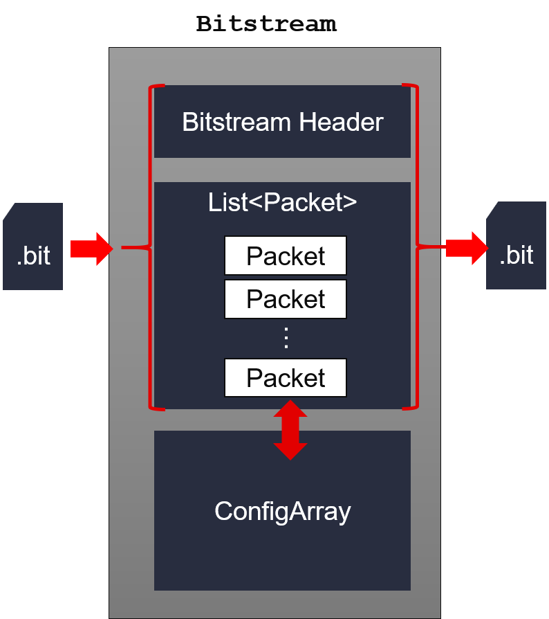
There are two ways to represent a bitstream in RapidWright. The first
is through a packet stream model represented by the Bitstream
class. The second is a configuration array model (see ConfigArray
class) that loosely represents the memory array of the device as
configured by the packets delivered from the bitstream. Each model is
briefly described below.
Bitstream Packet Model
A .bit file is essentially a sequence of packets that contain
instructions to read and write configuration registers (see
configuration user guides above for greater details). RapidWright has
several class objects that will parse and represent the difference
components of a bitstream using the Bitstream,
BitstreamHeader, Packet, OpCode, PacketType and
RegisterType classes and enums. A key point is that a
bitstream contains a list of packets that read and write registers.
One register in particular is the Frame Data Register (FDRI) that
writes and read data to the configuration memory of the device.
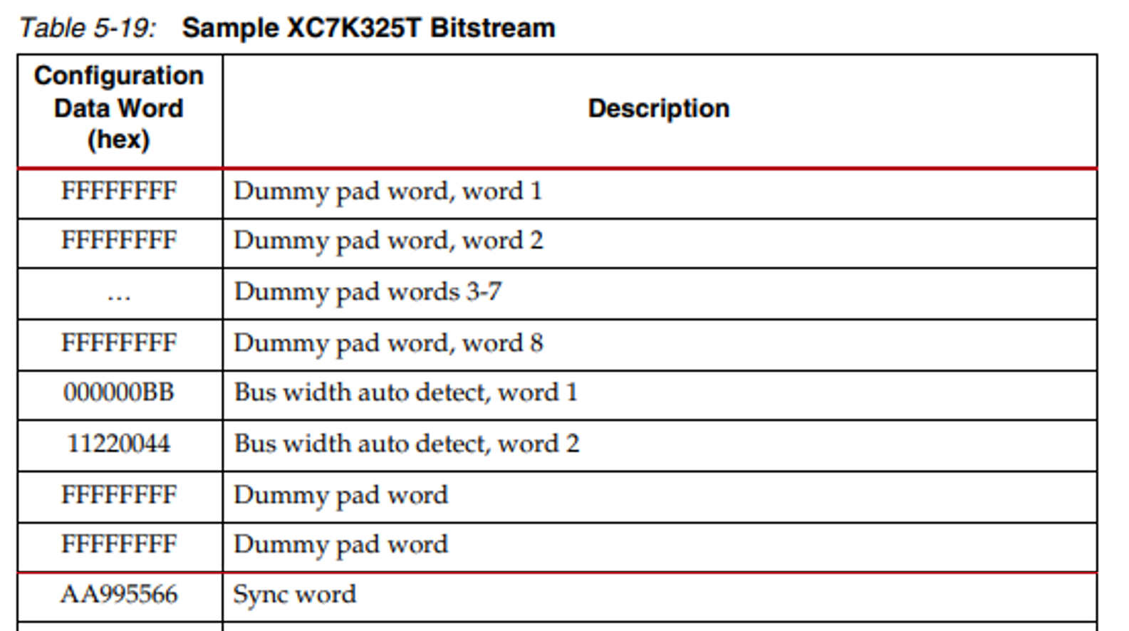
BitstreamHeader
The bitstream header appears at the beginning of a .bit file and is a list of 32-bit words that contain some metadata about the bitstream (creation date/time, target part name, design name, etc). It also contains some dummy pad words and bus width detection packets. The header ends with the sync word (0xAA995566), an example is shown from an excerpt of a Series 7 below:
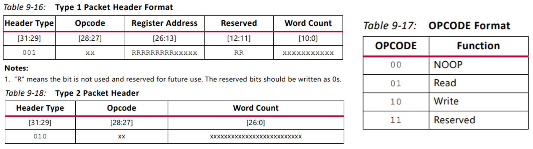
Packet and PacketType
Each packet has a header word (32-bits) and often a payload. There are two kinds of packets, most of which are of type 1. Type 2 packets are used for very large payloads (such as configuration array data). Bit fields are shown below from the configuration user guide:
RegisterType and Frame Address Register
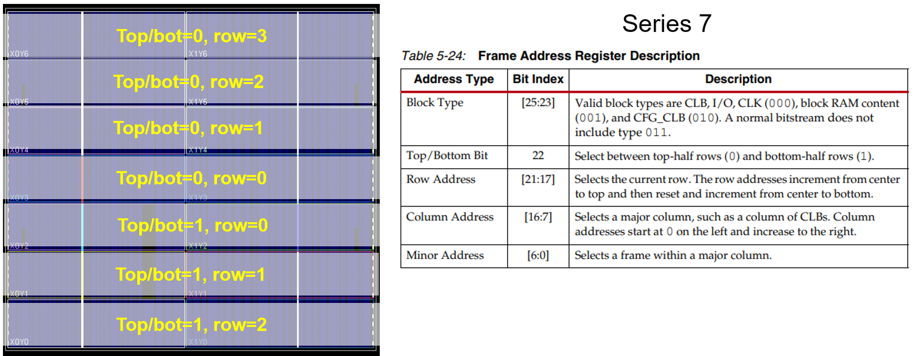
There are several configuration register types, please refer to your architecture’s respective guide (listed above) for details. One of the most import registers used is the frame address register (FAR). The FAR describes the address to which a frame a configuration data is written to in the configuration array.
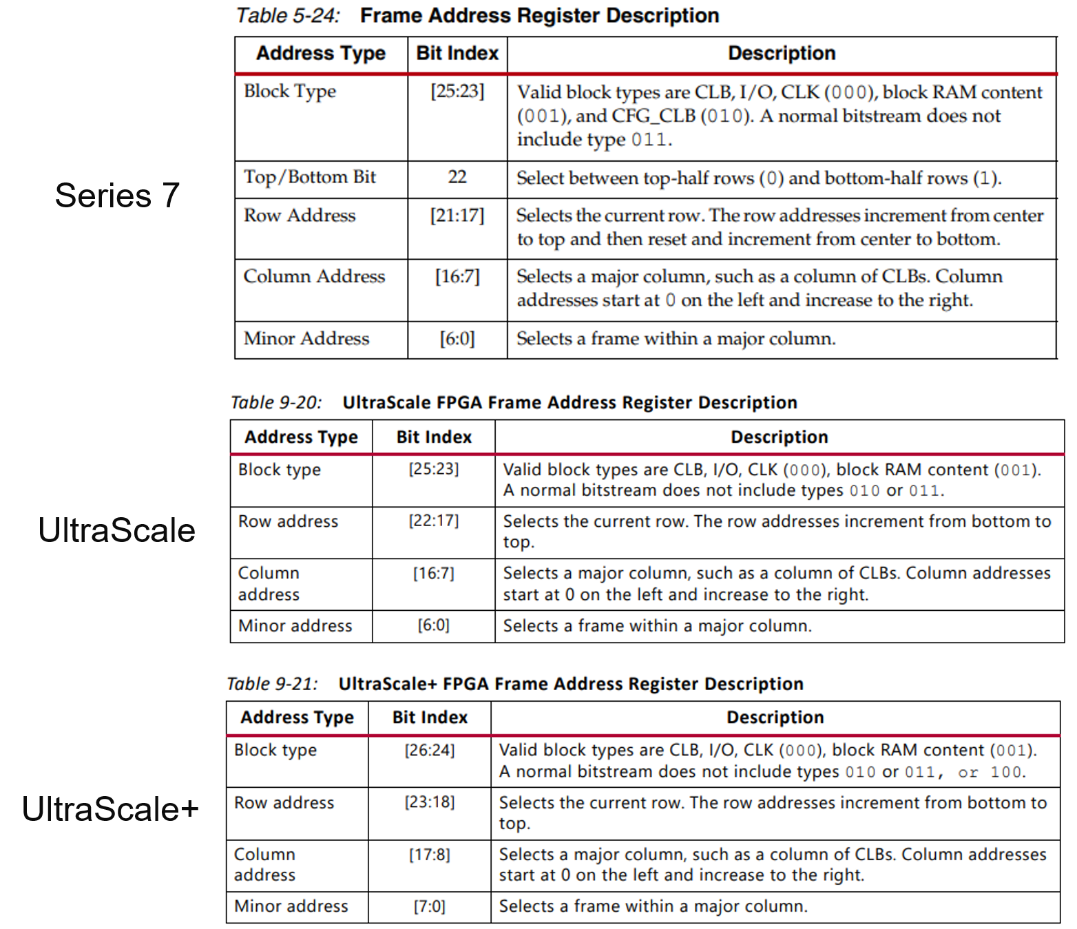
The configuration array is divided into smaller segments called configuration rows, rows are divided into columns of blocks and then each unique block is divided into a number of frames. A block is the same height as a clock region in the fabric.
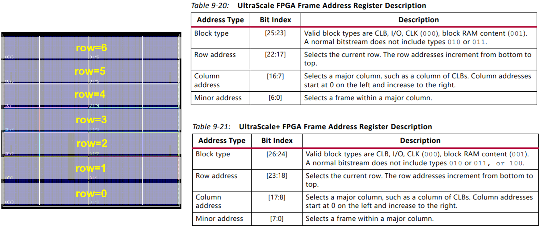
A frame address has several fields that are architecture specific. See the tables above for the bit fields used. For example, a Series 7 device distinguishes the top and bottom half of a device as a separate region whereas for UltraScale and UltraScale+ this is not the case. See figures below for to illustrate:
When a frame of data is written to the FDRI, the FAR register automatically increment each time a complete frame of data is written. Thus, no additional packets to set the FAR are necessary, although there are debug CRC bitstreams that can be generated where the FAR address is set explicitly for each frame (see UG908- Table A-1, BITSTREAM.GENERAL.DEBUGBITSTREAM YES).
Configuration Array Model
The ConfigArray class represents the array as defined by the
address space of the FAR and holds all the frame data written to it by
the packet list from the bitstream. The config array is essentially a
list of configuration rows, each row is a list of configuration blocks
and each block is a list of configuration frames.
Example Usages: Modify User State Bits
Note
The API ConfigArray.updateUserStateBits() only updates user state bits as documented in the logic location file generated from write_bitstream -logic_location_file.
public static void main(String[] args) {
  Design design = Design.readCheckpoint(args[0]);
  Bitstream bitstream = Bitstream.readBitstream(args[1]);
  ConfigArray configArray = bitstream.configureArray();

  // Changes the initialization of the FF to 1
  Cell cell = design.getCell("myFF");
  cell.getProperty("INIT").setValue("1");
  configArray.updateUserStateBits(cell);
  bitstream.updatePacketsFromConfigArray();

  design.writeCheckpoint(args[2]);
  bitstream.writeBitstream(args[3]);
}
Example Usages: Find and Print the Frames of a Placed Cell
public static void main(String[] args) {
  Design design = Design.readCheckpoint(args[0]);
  Bitstream bitstream = Bitstream.readBitstream(args[1]);
  ConfigArray configArray = bitstream.configureArray();

  // Find Configuration Block of a resource and print frames
  Cell cell = design.getCell("myFF");
  Block block = configArray.getConfigBlock(cell.getTile());
  for(Frame frame : block.getFrames()) {
    System.out.println(frame.toString(true));
  }
}